Recipe 1: Generating surface of bone from CT.
(Or any other feature that can be segmented using a threshold.)
Part A: Data for manipulation operations (BS0 data)
- Select an IM0 data file in PREPROCESS->SceneOperations->Input.
- Goto PREPROCESS->SceneOperations->Segment->Threshold.
- Keep the cursor on the IMAGE window and,
- Press LEFT mouse button for "SELECT INTERVAL".
- Move the mouse and observe the lower threshold limit being
displayed below the histogram. Press the LEFT mouse button to
specify the "INITIAL POINT" (lower limit).
- Now moving the mouse will display the upper threshold
limit. Once the correct upper limit is selected upon press the
MIDDLE mouse button to specify it.
- Now the thresholded boundary should be displayed on the
right of the histogram. If the selection is incorrect repeat
step 3.

- Bring the cursor down to the panel button "OUTPUT | BIM" in the
DIALOG window and press the MIDDLE mouse button. The option should
now show "OUTPUT | BS0".
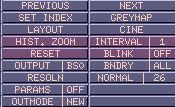
- Move the mouse the BUTTON window and observe the row that has
the "OUTPUT | 1" and "SAVE" buttons. Between these two is the text
item of the output file name. You can change the file name by first
clicking the LEFT mouse button on the tablet and then typing in
the new file name. Once a new file name has been entered press the
LEFT mouse button on the "SAVE" button on that same row to generate
the surface data.
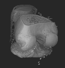
- To visualize the data first select the file you saved in 5 from
MANIPULATE->Input and the goto MANIPULATE->Move. Now you should
see the surface you generated.
- The same procedure can be executed by running the following
unix script, copy this to a file and give execute permission
(chmod +x script_file) to the script
#!/bin/sh

case $# in
       	4)
       	track_all $1.IM0 $2.BS0 1.0 $3 $4 26 0 0
       	track_all $1.IM0 $2.BSI 4.0 $3 $4 8 0 0
       	;;
       	*)
       	echo "Usage: " $0 "   low_thresh hi_thresh "
       	echo "  infile     - IM0 file without the extension"
       	echo "  outfile    - BS0 file without the extension"
       	echo "  low_thresh - lower threshold limit"
       	echo "  hi_thresh  - upper threshold limit"
	echo "This would take an IM0 file and produce a BS0 surface."
       	;;
esac
Part B: Generate a Fuzzy Surface for Volume Rendering
- Select a IM0 data file from PREPROCESS->SceneOperations->Input.
- Goto PREPROCESS->SceneOperations->Classify->1Feature.
- Goto the panel option "MATERL | ALL" in the DIALOG window.
Press the LEFT mouse button so that the option shows "MATERL | ONE".

- Goto the panel option "CLSFN.FN | 1" and press the LEFT mouse
button three times. The option should now show "CLSFN.FN | 4".
- Move the mouse to the IMAGE window and,
- Press the LEFT mouse button once and move the mouse to
observe the lower most intensity limit of the surface. Once the
limit is decided press the LEFT mouse button.
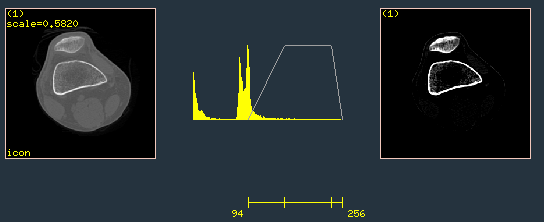
- Observe the slanted line on the histogram when moving the
mouse. This indicate the gradually increasing surface tissue
percentage of the object. Press the LEFT mouse button to select upper
limit (100%) of this segment.
- Now observe the horizontal line segment displayed when
moving the mouse. This intensity region indicates the strong
surface region (100%) of the object. Press the LEFT mouse button to
select the end of this horizontal segment.
- Now when moving the mouse you should see another slanted
line which indicates the upper most intensity indicating the
gradually decreasing tissue percentage of this surface. Press the
MIDDLE mouse button to select this value.
- Now you should be able to see the fuzzy surface you
selected on the image to the right of the histogram. The strong
boundary points should appear white in this display. If the
selection is incorrect repeat step 5.
- Move the mouse to the BUTTON window and observe the row that has
the "OUTPUT | 1" and "SAVE" buttons. Press the LEFT mouse button
three times on the "OUTPUT | 1" button such that it now shows
"OUTPUT | 4". Between "OUTPUT | 4" and "SAVE" buttons is the text
item for the output file name. You can change the file name by first
clicking the LEFT mouse button on the text item and then typing in
the new file name.

- Once a new file name has been entered press the LEFT mouse button
on the "SAVE" button on that same row to output the surface data.
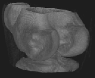
- To visualize the data first select the file you saved in 7 from
VISUALIZE->Volume->Input and then goto VISUALIZE->Volume->View to
visualize the surface you generated.
Recipe 2: Generating surface data from segmented binary data set (BIM data)
Part A: Data for manipulation operations (BS0 data)
- The segmentation can be done through many modules. You should
be able to generate BIM file by
- PORTING a 1 bit dataset from PORT-DATA->In->EasyHeader.
- From PREPROCESS->SceneOperations->Segment->Threshold.
- If you have two registered features (like proton density and
T2 images of MR) PREPROCESS->SceneOperations->Segment->2Features.
- If you want to manually out line the structure on the gray
data PREPROCESS->SceneOperations->Segment->Interactive2D.
- Select the BIM file from PREPROCESS->SceneOperations->Input.
- Goto PREPROCESS->SceneOperations->Interpolate. Press the LEFT
mouse button on the panel option "X3 | N.N." once, so it shows
"X3 | LINR".
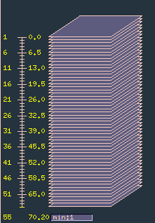

- Goto the BUTTON window and press the LEFT mouse button over the
top most "SAVE" button. This will generate an interpolated binary
file called intrpl-tmp.BIM .
- Select this BIM file from PREPROCESS->SceneOperations->Input.
- Goto PREPROCESS->SceneOperations->Filter. Move the cursor to
the panel item "TYPE | Gauss2D" to "TYPE | Gauss3D" by pressing
the LEFT mouse button.
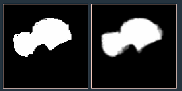
- Goto the BUTTON window and press the LEFT button on the top
most "SAVE" button. This will generate a filtered gray data file
called filter-tmp.IM0 .
- Use this file and follow the steps given for [1]-(A) using
the values 110 and 255 for the lower and upper limits for steps
1-3.
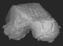
- The same procedure can be executed by running the following
unix script, copy this to a file and give execute permission
(chmod +x script_file) to the script
#!/bin/sh

case $# in
        2)
        shape_interp_cb $1.BIM $$INT.BIM 0
        gaussian3d $$INT.BIM $$INT.IM0 0 1.5
        rm $$INT.BIM
        track_all $$INT.IM0 $2.BS0 1.0 110 256 26 0 0
        track_all $$INT.IM0 $2.BSI 4.0 110 256 8 0 0
        rm $$INT.IM0
        ;;
        *)
        echo "Usage: " $0 "  "
        echo "  infile - BIM file without the extension"
        echo " outfile - BS0 file without the extension"
        echo "This would take an BIM file and produce a BS0 surface"
        echo "This would work only for 3d IM0 files."
        ;;
esac
Part B: To get a smoother version of the surface generated in Part A
- Goto PREPROCESS->SceneOperations->Filter. Move the cursor to
the panel item "TYPE | Gauss2D" and change it to "TYPE | Gauss3D" by
pressing the LEFT mouse button once over it.
- Goto the BUTTON window and press the LEFT mouse button on the top
most "SAVE" button. This will generate a filtered gray data file
called filter-tmp.IM0 .
- Select the filter-tmp.IM0 file saved above using
PREPROCESS->SceneOperations->Input.
- Goto PREPROCESS->SceneOperations->Segment->Threshold.
- Keep the mouse on the IMAGE window and,
- Press LEFT mouse button for "SELECT INTERVAL".
- Move the mouse and observe the lower threshold limit being
displayed below the histogram. Press the LEFT mouse button to
select the "INITIAL POINT" when the values is at 110.
- Now moving the mouse will display the upper threshold
limit. Once the upper limit is at 255 press the MIDDLE mouse button
to select it.
- Now the thresholded region should be displayed on the
right of the histogram. If the selection is incorrect repeat
step 5.
- Move the cursor to the BUTTON window and press the LEFT mouse
button on the top most "SAVE" button. This will generate a
thresholded data file called thrsld-tmp1.IM0.
- Select the thrsld-tmp1.BIM file saved above using
PREPROCESS->SceneOperations->Input. Follow steps in Recipe 2, Part A.

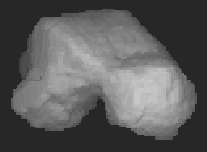
#!/bin/sh

case $# in
        2)
        gaussian3d $1.BIM $$FILT.IM0 0 1.5
        ndthreshold $$FILT.IM0 $$BIN.BIM 0 110 255
        rm $$FILT.IM0
        shape_interp_cb $$BIN.BIM $$INT.BIM 0
        rm $$BIN.BIM
        track_all $$INT.BIM $1.BS0  1.0 0.5 1.0 0 0 0
        track_all $$INT.BIM $1.BSI  4.0 0.5 1.0 0 0 0
        gaussian3d $$INT.BIM $$INT.IM0 0 1.5
        rm $$INT.BIM
        to_normal $2.BS0 1 $$INT.IM0 0 26 0
        to_normal $2.BSI 1 $$INT.IM0 0 8 0
        rm $$INT.IM0
        ;;
        *)
        echo "Usage: " $0 "  "
        echo "  infile - BIM file without the extension"
        echo " outfile - BS0 file without the extension"
        echo "This would take an BIM file and produce a BS0 surface"
        echo "This would work only for 3d IM0 files."
        ;;
esac


 User Manual
 Library Ref. Manual
 Tutorial
