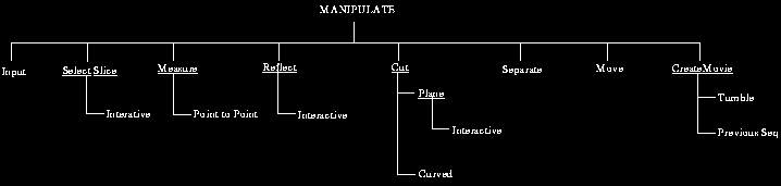
Fig 11.1: Commands Under MANIPULATE.
Fig 11.1: Commands Under MANIPULATE.
The main purpose of MANIPULATE commands is to allow manipulation of
structures, structure systems, and structure plans so as to produce new
structures, structure systems or structure plans.
11.1 Summary of Commands
Input allows selecting input files of type BS0 containing binary Shell0
structures representing a structure system, or PLN containing structure
plans. The purpose of SelectSlice is to allow selection of any arbitrary
plane through the structures and to compute and display cell intensity
distribution in this plane. The input structures may be derived from
multiple scenes in which case the appropriate scenes are automatically
selected for this computation. If a structure system is created based on
structures derived from multiple imaging modalities with proper
registration, this command allows comparing the "same" slice from
different scenes coming from different modalities. Measure's function is
to allow various types of measurements to be made by pointing to
locations on the surface of the structures. The purpose of Reflect is to
reflect the part of the structures on one side of the specified
reflecting plane to the other side and to selectively visualize the
reflected structures with the original structures in any combination.
The function of Cut is to allow cutting of structures using planes or
curved surfaces and retaining the part on the selected side of the plane
or of the surface. Separate allows cutting a structure into two parts
using planar or curved cutting surfaces. Each of these parts becomes a
new structure which can be subjected to any of the MANIPULATE
operations. Move allows moving a selected structure or group of
structures relative to the rest of the structures in the structure
system with any translation and rotation. CreateMovie is for creating
animation sequences resulting from the display of the structure system
in various viewing angles.
We wish to emphasize that although these commands are independent, they
operate on the result created by other MANIPULATE commands that have
operated on the structures previously. For example, you may select one
particular structure, Separate it into two parts, Move one of them,
Reflect the structures about a selected plane, and then Measure. It is
up to the imagination of the user and the requirements of the
application at hand as to how the commands could and should be mixed and
ordered. In its present form, MANIPULATE does not handle structure
systems with dynamic structures. Although some of the MANIPULATE
operations do apply and are useful in the case of dynamic objects, some
do not make sense. Therefore, MANIPULATE commands at present recognize
no parameter in the parameter vector.
11.2 Common Options
OPACITY: This option is a switch with two states FULL (default) and
HALF. In state FULL, the chosen object (indicated in switch OBJECT) is
displayed at 100% opacity, and in HALF, it is made semitransparent.
MAGNIFY: This is a button which allows changing the magnification of the objects in the rendition. When this option is selected, a scale is set up to specify the magnification factor. A value of 1 on this scale corresponds to display of the structure system in life size. Some parts of the structure system may fall outside the frame of the rendition for certain magnification factors. These may be brought within the frame using the SCROLL option. All objects in the structure system are displayed always at the same magnification.
The default value is set up so as to give an image of reasonable size that captures all aspects of the structure system. If the objects are very large, it may not be possible to capture within the screen their full rendition with sufficient detail. For fast interactive display, a low magnification value should be selected. An optimal value that gives sufficient speed as well as size and details of rendition depends on the power of the machine on which 3DVIEWNIX resides.
SCROLL: This is a button which allows scrolling the rendition within the image window using mouse movement. Its state diagram is shown in Figure 11.2. This option should be terminated by clicking the right button before other options can be selected.
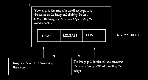
Fig 11.2: State diagram for the panel option SCROLL in MANIPULATE. An arrow
leaving a mouse button area indicates that that button has been clicked.
BOX: This is a switch with two states, ON and OFF. When the state is ON, a wire-frame box indicating the domain of the structures and enclosing the structures is displayed in the rendition. It serves to show the orientation of the coordinate system associated with the structures relative to the view space coordinate system.
REMOVE: This is a button which allows removing objects that are created during the current session with MANIPULATE. For example, Reflect creates objects that are reflections of certain parts of the input structures. These can be deleted from the display by selecting the appropriate object number via the option (switch) OBJECT and then selecting REMOVE. This option does not delete original input objects.
Several MANIPULATE commands generate new objects. If the input itself contains many objects, it may become confusing as to what the various object numbers represent. An easy way of keeping track of objects is to turn on all of them and use the option SELECT OBJECT (middle mouse button in state 1 of all MANIPULATE commands) when the cursor is pointing at the object in the rendition. The switch OBJECT now changes to the number of the object pointed to. You may delete that object using REMOVE if you do not want to retain it. If you do not assign different colors to the different objects, you may not be able to distinguish between them in the display. Removal is always upon confirmation as shown in the state diagram of Figure 11.3 associated with this option.
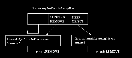
Fig 11.3: State diagram for panel option REMOVE of MANIPULATE. An arrow
leaving a mouse button area indicates that that button has been clicked.
11.3 Commands
11.3.1 Input
This command should be used for selecting the desired BS0 input files
containing the structures to be visualized. Multiple files can be
selected, in which case the coordinate system specified in each file for
the structures contained in it is assumed to be relative to a common
imaging device coordinate system. If the structures in different files
are derived from different scenes which in turn are obtained from
different imaging devices, this assumption may not be valid. In the
latter case, the structures may not be in their correct spatial and
geometric relationship. Where multiple structures derived from multiple
imaging devices are to be manipulated, the best approach is to first
create a structure system in a single file in which the structures are
properly registered and then use this as input file to MANIPULATE.
For a description of the operation of Input, see Section 7.2.
11.3.2 SelectSlice
The purpose of this command is to make it possible to interactively
select an arbitrary plane passing through a selected object in the input
files and to compute and display cell intensity distribution in the
plane within the scene from which the object was derived. If the number
of scenes from which the input objects are derived is more than one, the
slice computed from each of these scenes can be displayed. Two such
slices can be displayed, one overlaid on the other in a translucent
mode. The scenes from which the objects are derived are determined
automatically from the information contained in the input files. It is,
therefore, important for the successful execution of this command that
the input files are created correctly and that the files containing
these scenes are currently available. The color chosen for the slice
display is the same as the color chosen for the object (via the panel
button COLOR) for which SelectSlice is being applied. In order for the
computed slice of a particular scene to be displayed, the status of that
scene should be set to ON via the switches SCENE and OBJECT. The
location and size of the display of the computed slice are interactively
specified by the user via the mouse button options as illustrated in
Figure 11.4. To create an overlaid display of computed slices derived
from two different scenes, first set the status of the two scenes to ON
via the switches SCENE and OBJECT and choose color of the two
corresponding objects via the switches OBJECT and COLOR. Subsequently,
select the slice and display it at an appropriate location and size.
If a MANIPULATE command has previously been selected, the display situation arrived at in that command is left intact for continuation in SelectSlice-Interactive. Otherwise, a proper rendition with appropriate rendering parameters should be first created by selecting the relevant panel options of SelectSlice-Interactive.
At present, the only command available under SelectSlice is Interactive. The state diagram for this command is shown in Figure 11.4. As soon as SelectSlice-Interactive is selected, a rendition of the input structures is created on the left and a display of the icon is created on the right. In both displays a default plane is also shown. The default plane location is at the center of the box that encloses all structures and the default orientation is parallel to the xy-plane of the view space. The plane orientation and location can be changed interactively using the mouse and its options as illustrated in Figure 11.4.
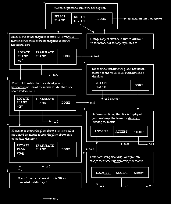
Fig 11.4: State diagram for SelectSlice-Interactive. An arrow leaving a
button area indicates that that button has been clicked.
The panel options available under this command are shown in Figure 11.5.
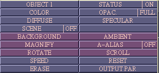
Fig 11.5: Panel options for SelectSlice-Interactive.
RESET: This is a button which when selected sets plane to its default location and orientation. It does not change the orientation of the objects.
The remaining options work as described in Sections 7.2 and 11.2.
OUTPUT PAR: This option is a button whose purpose is to specify the output scene parameters if the user intends to create a scene by reslicing the objects. The mouse button states associated with this option are shown in Figure 11.6. The parameters include the first and last location of plane to indicate the extent of the domain of the output scene and the size of the cells in the output scene. MANIPULATE in its present form does not handle time varying objects, and hence, the scenes from which structures are derived are assumed to be three-dimensional. The parameters related to output scene resolution to be specified are, therefore, pixel size and slice spacing.
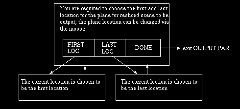
Fig 11.6: State diagram for OUTPUT PAR option in SelectSlice-Interactive.
An arrow leaving a button area indicates that that button has been clicked.
SCENE: This is a switch which together with the OBJECT switch allows
selecting a scene or a combination of scenes for the display of the
computed slices. To select a scene, set OBJECT to the desired number and
set SCENE to ON. At most two scenes can be set to ON simultaneously.
This is mainly because any display of more than two scenes in an overlay
fashion becomes very difficult to understand. The default setting for
SCENE is the same as the STATUS setting of the object selected for
reslicing and OFF for the rest.
If a MANIPULATE command has previously been selected, the display
situation arrived at in that command is left intact for continuation in
Measure. Otherwise, a proper rendition with appropriate rendering
parameters should be first created by selecting relevant panel options
in Measure. The only command available under Measure at present is
PointToPoint.
The state diagram for Measure-PointToPoint is shown in Figure 11.7. By
pointing to a location in the rendition, the user points to a location
on a structure surface. When a translucent surface is in front of an
opaque surface, the ambiguity as to which surface is pointed at is
resolved via the switch MEAS. This assumes two states, called OP and TR
indicating respectively the opaque and translucent surface. The measures
computed and displayed in the dialog window are: total length of line
segments connecting the successive points specified on the structures,
the length of the most recent line segment, and the angle between the
most recent two line segments. Note that the points selected need not
all be on the same structure or in the same view. The measuring process
can be suspended for selection of any panel options and subsequently
resumed.
The panel options available under Measure-PointToPoint are shown in
Figure 11.8.
RESET: This option is a button which when selected removes the overlay
display that indicates the points selected while measuring and the lines
that connect the points. It also resets all measures so that the
measurement process can start afresh.
MARKS: This is a switch with two states ON and OFF. In its ON state, it
displays any previously laid marks and allows laying marks on the
structure surfaces. In the OFF state, the display of the marks is
removed, although the marks themselves are not removed. The marks can be
used as artificial landmarks for guiding the manipulation and
measurement process.
SET MARKS: This is a button that allows putting marks on the input
structure surfaces. When the option is selected, it turns MARKS to the
ON state and proceeds as indicated in the state diagram of Figure 11.9
with the marking process.
The marks become a part of the structure on which they are set and they
will appear in the correct location even when the structure is rotated,
magnified, scrolled, cut, separated, reflected and moved via other
commands and options. They can be removed via the ERASE MARKS option.
ERASE MARKS: This is a button which when selected turns MARKS to the ON
state and proceeds as indicated in Figure 10.34 (under Volume-Measure)
with the removal of previously set marks.
MEAS: This is a switch with two states, OP and TR. Its purpose is to
allow the user to specify unequivocally the surface which is pointed at
in the case when a translucent surface appears in front of an opaque
surface in the rendition at the point indicated. When the state is OP,
the surface is assumed to be that of the opaque structure and that of
the translucent structures in the other case. When multiple translucent
structures appear at a point, the point indicated is assumed to be on
the structure that is closest to the viewer at that point.
Other options in Measure-PointToPoint are as described in Sections 7.2
and 11.2.
If a MANIPULATE command has previously been selected, the display
situation arrived at in that command is left intact for continuation in
Reflect-Interactive. Otherwise, a proper rendition with appropriate
rendering parameters should be first created by selecting the
appropriate panel options of Reflect-Interactive.
At the present, the only command available under Reflect is Interactive.
The state diagram associated with this command is shown in Figure 11.10.
The panel options for this command are shown in Figure 11.11.
RESET: This is a button which when selected sets the plane location and
orientation to the default setting (which is the center of the box
enclosing all structures and parallel to the xy-plane of view space) and
computes and displays a reflected object for every object whose
reflection status is on.
The remaining options work as described in Sections 7.2 and 11.2.
All MANIPULATE commands and all panel options available are applicable
to the newly created objects. That is, these objects' display
characteristics can be changed independently, and they can be used for
selecting slice, measured, further cut, separated, moved, and animated.
If a MANIPULATE command has previously been selected, the display
situation arrived at in that command is left intact for continuation in
Cut-Plane-Interactive. Otherwise, a proper rendition with appropriate
rendering parameters should be first created by selecting the
appropriate panel options of Cut-Plane-Interactive.
The state diagram for this command is identical to that of
Reflect-Interactive shown in Figure 11.10. The only difference in this
command is that the selected side (in state 6) is retained after the cut
operation rather than reflected as in Reflect-Interactive.
The panel options available under this command are shown in Figure
11.12.
RESET: This option is a button, which upon selection removes the just
created new object and restores in the display the original object from
which it was cut. Thus, after resetting, the number of objects becomes
one less.
The remaining options work as described in Sections 7.2 and 11.2.
The new object assembly created by this command and possibly modified by
other MANIPULATE commands can be saved in a PLN and a BS0 file. The
reason for creating a PLN file is that the positional relationship of
objects may be changed by the Move command. To create an output, turn on
the desired objects, enter a desired output file name in the tablet in
the mouse window in the output section, and then select SAVE. The output
operation will not take place if the objects selected are not all of the
same resolution.
The behavior of this command as to the new objects created and their
number is identical to that of Cut-Plane-Interactive. See Section
11.3.5.1 for details. All MANIPULATE commands and their options are
applicable to the newly created objects. That is, these objects' display
characteristics can be changed independently, and they can be used for
selecting slice, measured, further cut, separated, moved, and animated.
If a MANIPULATE command has previously been selected, the display
situation arrived at in that command is left intact for continuation in
Cut-Curved. Otherwise, a proper rendition with appropriate rendering
parameters should be first created by selecting the appropriate panel
options of Cut-Curved.
The panel options available for this command are as for
Cut-Plane-Interactive (Figure 11.12). RESET functions as for
Cut-Plane-Interactive. The remaining options work as described in
Sections 7.2 and 11.2.
The new object assembly created by this command and possibly modified by
other MANIPULATE commands can be saved in a PLN and a BS0 file. The
reason for creating a PLN file is that the positional relationship of
objects may be changed by the Move command. To create an output, turn on
the desired objects, enter a desired output file name in the tablet in
the mouse window in the output section, and then select SAVE. The output
operation will not take place if the objects selected are not all of the
same resolution.
As in Cut, Separate requires that only one object be turned on since it
can operate only on one object at a time. This object should not be a
reflected object (that is, those having a negative number). The cutting
is done by curved surfaces as in Cut-Curved. The cutting operation,
therefore, proceeds exactly as in Cut-Curved. The main deviation is that
both parts are shown at all times and the user is allowed to cut either
of the two parts. At the beginning of this operation, the primary part
(displayed on the left in the image window) is the whole of the selected
object and the secondary part (displayed on the right of the image
window) is empty. When a cut is made on one part, the cut segment is
added to the other part. Thus, during the Separate operation, the sum of
the primary and secondary parts always equals the whole object. The
important thing to note is that the two parts can be rotated
independently using the ROTATE OBJ panel option and the Separate
operation can be continued after rotation. The selected object can thus
be separated into two parts (new objects) in a sophisticated way.
The two new objects created get numbers n+1 (primary part) and n+2
(secondary part), where n is the total number of objects at the time the
Separate operation began. The new objects become effective when Separate
is quit, or when certain options within Separate are chosen, such as
selecting a new object to operate on.
The state diagram associated with this command is identical to that of
Cut-Curved (Figure 11.13), except that, in states 5 and 6, the
complement of the retained part is added to the part other than what is
being operated on.
If a MANIPULATE command has previously been selected prior to Separate,
the display situation arrived at in that command is left intact for
continuation in Separate. Otherwise, a proper rendition with appropriate
rendering parameters should be first created by selecting appropriate
panel options of Separate.
The panel options for Separate are identical to those for
Reflect-Interactive. The function of RESET is to essentially remove the
effect of the current operation of Separate if you hae not left
Separate. That is, RESET deletes the current primary and secondary
parts, sets the object selected for the Separate operation to be the
primary part and makes the secondary part empty. You can leave Separate,
to move one of the parts for instance, and then come back and continue
the operation. In this case, RESET restores the parts as they were the
first time you entered Separate.
If a MANIPULATE command has previously been selected prior to Move, the
display situation arrived at in that command is left intact for
continuation in Move. Otherwise, a proper rendition with appropriate
rendering parameters should be first created by selecting appropriate
panel options of Move.
The panel options for Move are shown in Figure 11.15.
Note that the ROTATE OBJ panel option rotates all objects starting from
their current position.
RESET: This option is a button, which when selected, sets position of
all objects to that which existed when they were loaded. In other words,
it undoes the effect of the move operation.
MOBILE: This is a switch with two states, ON and OFF. In the OFF state,
the objects selected cannot be moved. The state should be set to ON for
moving the objects.
The remaining options in Move work as described in Sections 7.2 and
11.2.
This command does not create new objects. But it can change the
positional relationship of the objects. It can therefore be used to
create and output a structure plan. It simultaneously also outputs a
structure system consisting of all input structures that are turned on.
It is important, however, that the objects that are turned on be all of
the same resolution. If this condition is not met, no output is made. To
create and output a structure system and plan, manipulate the input
objects via Cut, Separate, and Move, enter the desired output file name
in the tablet, and select the SAVE option.
At present, the movie must be created in the foreground mode; therefore,
the RUN-MODE switch in the mouse window is not displayed.
Obviously, any rotation sequence can be specified using the above
mechanism of the key poses. As a simple example, consider how a complete
360 movie sequence may be specified for rotation about the x-axis
starting from some initial orientation of the object assembly. We choose
the starting orientation to be the first key pose. Then rotate the
object assembly around the x-axis by 120 and select the resulting
orientation to be the second key pose. Choose another key pose after
rotation by another 120 about x-axis, and subsequently close the
sequence.
The panel options available for this command are shown in Figure 11.17.
DEL POSE: This option, available as a button, allows deleting the most
recently specified key pose. The option may be selected in states 5 or 6
of Figure 11.16.
PREVIEW: This option, implemented as a button, is for getting a preview
of the movie that is to be created for the sequence of key poses that
has been specified. The associated state diagram is shown in Figure
11.18. In states 2 and 3, "next frame" is determined by the state of the
panel switches D.MODE and POSES.
D. MODE: This is a switch with two states, ICON and FULL, FULL being the
default state. When the state is ICON, only renditions of the ICON are
shown in the PREVIEW option. When the state is FULL, only the FULL
resolution renditions are shown in PREVIEW.
POSES: This is a switch with two states, KEY and ALL. KEY being the
default state. When the state is KEY, only key poses selected are shown
in PREVIEW. In state ALL, all poses, including the intermediate ones,
are shown in PREVIEW. The four possible combination of the states of
D.MODE and POSES can be used to create a desired mode for PREVIEW.
The states D.MODE and POSES apply only to PREVIEW. While actually
creating the movie, always the views corresponding to ALL poses and FULL
resolution are generated.
To create a movie, simply select the SAVE option for OUTPUT in the mouse
window. The panel options for this command are shown in Figure 11.19.
These options have already been described in Sections 7.2 and 11.2. If
you do not select SAVE, subsequent sequences will be appended to the
same movie until you exit the CreateMovie command, when the movie will
be saved.
11.3.3 Measure
The main purpose of this command is to allow making linear, curvilinear
and angular measurements by directly pointing to locations on surfaces
of structures via their renditions.
Fig 11.7: State diagram for Measure-PointToPoint. An arrow leaving a mouse
button area indicates that that button has been clicked.
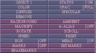
Fig 11.8: Panel Option for Measure-PointToPoint.
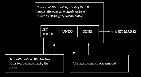
Fig 11.9: State diagram for the option SET MARKS of Measure-PointToPoint.
An arrow leaving a mouse button area indicates that that button has been
clicked.
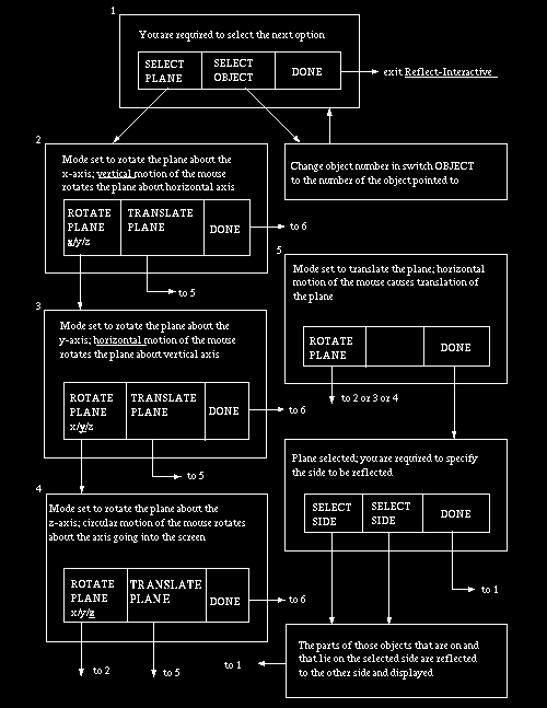
Fig 11.10: State diagram for Reflect-Interactive. An arrow leaving a mouse
button area indicates that that button has been clicked.
11.3.4 Reflect
The purpose of this command is to make it possible to interactively
select an arbitrary plane and to compute and display mirror reflections
about the plane of those parts of the input objects lying on a specified
side of the plane. The reflection is computed for each object whose
STATUS is ON, and is treated as an additional object. This number
assigned to a reflection is x where x is the number of the object that
is reflected. Each reflected object can be turned on or off via switches
OBJECT and STATUS. Its display characteristics such as color, opacity,
diffuse and specular properties can be specified independently as for
other objects. For distinguishability, the display characteristics of
reflected objects should be properly chosen in relation to other objects
that are displayed.
Fig 11.11: Panel options for Reflect-Interactive, and Separate.
11.3.5 Cut
There are two commands available under Cut, one for cutting by a plane,
called Cut-Plane-Interactive, and the other for cutting by a curved
surface called Cut-Curved.
11.3.5.1 Cut-Plane-Interactive
This command allows selecting a plane interactively as in
SelectSlice-Interactive and Reflect-Interactive, cutting a selected
object using the plane, and retaining the part of the object on the
selected side of the plane. While using this command, only one object
should be on. That is, the command allows cutting only one object at a
time. This object should not be a reflected object (that is, an object
with a negative number). When an object is cut, the retained part
becomes a new object which is assigned the number n+1 where n is the
current total number of objects prior to the cutting operation. The
object that is operated on is retained and its number does not change.
For example, suppose we have three objects altogether in the input files
and that we cut two objects, object 1 first and then object 3. After the
first cut, there will be 4 objects -- the three input objects plus the
part of object 1 retained which becomes object 4. After the second cut,
there will be 5 objects -- objects 1, 2, 3, 4 as in the previous case
plus object 5 which is the part of object 3 that is retained. Once the
Cut operation has commenced, object number cannot be changed via the
option OBJECT until Cut is quit, but the object currently being cut can
be modified by repeated Cut operation. The new object does not become
effective until Cut is exited, at which time the just modified object
becomes object n+1.
Fig 11.12: Panel options for Cut-Plane-Interactive and Cut-Curved.
11.3.5.2 Cut-Curved
This command allows making a curved cut of specified depth on a selected
object and retaining a specified part of the object. While using this
command, only one object should be on. That is, the command
Cut-Plane-Interactive allows cutting only one object at a time. This
object should not be a reflected object (that is, it should not have a
negative number). The curved cut is specified by drawing a piecewise
linear curve. The successive points of the linear segments are specified
as illustrated in the state diagram of Figure 11.13. Once a closed curve
is specified, the user is prompted to specify the side of this curve --
its interior or exterior -- which contains the part of the object that
is to be retained. The object is cut into two parts -- the part lying
inside the closed curve to a certain depth and the remaining part of the
object. The depth of cut may be the entire extent of the object or a
depth value currently indicated on a scale displayed in the dialog
window. The value may be modified prior to initiating the cut. The unit
of measurement for depth is the same as that for pixel size of the
original scene data, which is usually mm.
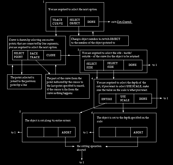
Fig 11.13: State diagram for Cut-Curved and Separate. An arrow leaving a
mouse button area indicates that that button has been clicked.
11.3.6 Separate
While Cut-Plane-Interactive and Cut-Curved commands allow cutting an
object and retaining only one part, Separate allows retaining both parts
each of which can be further rotated and cut.
11.3.7 Move
While most of the MANIPULATE commands discussed so far that allowed us
to create new objects do not change the relative position and
orientation of objects (note that the ROTATE OBJ option rotates the
whole assembly of objects), Move allows objects to be rotated and
translated relative to other objects in the assembly. Any group of
objects, except reflected objects, may be moved in this fashion. The
state diagram associated with this command is shown in Figure 11.14. Two
modes are available for move, called VIA POINTS and INTERACTIVE. In both
modes, a line is specified about/along which rotation/translation of the
selected objects is to be done. In VIA POINTS mode, the line is
specified by selecting two points on the surfaces. The line is assumed
to pass through these points. In INTERACTIVE mode, the line is specified
by rotating and translating a default or a most-recently specified
initial line.
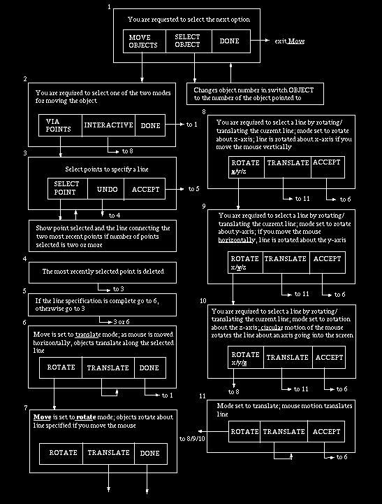
Fig 11.14: State diagram for Move. An arrow leaving a mouse button area
indicates that that button has been clicked.
Fig 11.15: Panel options for Move.
11.3.8 CreateMovie
The main purpose of these commands is to create and save in a file a
sequence of renditions depicting continuous rotations of the whole input
object assembly or of the whole assembly arrived at after manipulative
operations. There are two commands under CreateMovie: Tumble and
PrevSeq. Tumble allows creating a movie by arbitrary tumbling of the
object assembly. This works in a fashion analogous to
VISUALIZE-Volume-CreateMovie-Tumble. PrevSeq allows creating movies for
previously specified sequences of views. Its function is analogous to
that of VISUALIZE-Volume-CreateMovie-PrevSeq.
11.3.8.1 CreateMovie-Tumble
The state diagram for this command is shown in Figure 11.16. In order to
create a sequence of renditions, the user has to specify a set of key
poses of the object assembly. The number of intermediate views to be
generated for every pair of key poses should also be specified by the
user on a scale labelled INTERMEDIATE VIEWS. The time to specify this
number is after selecting a key pose (in state 5 in Figure 11.16). This
command generates the specified number of views by gradually changing
the orientation of the object assembly from the first key pose in the
pair to the second. A closed (cyclic) sequence can be generated by
making the next key pose to be the very first key pose specified. This
can be achieved via the CLOSE option in state 6. One may continue
specifying further key poses after closures and there may be any number
of closed loops of this form in the final sequence specified. The actual
generation of the movie sequence starts when the START MOVIE option is
selected in state 5. At that time the MAGNIFY option is disabled until
the movie is saved.
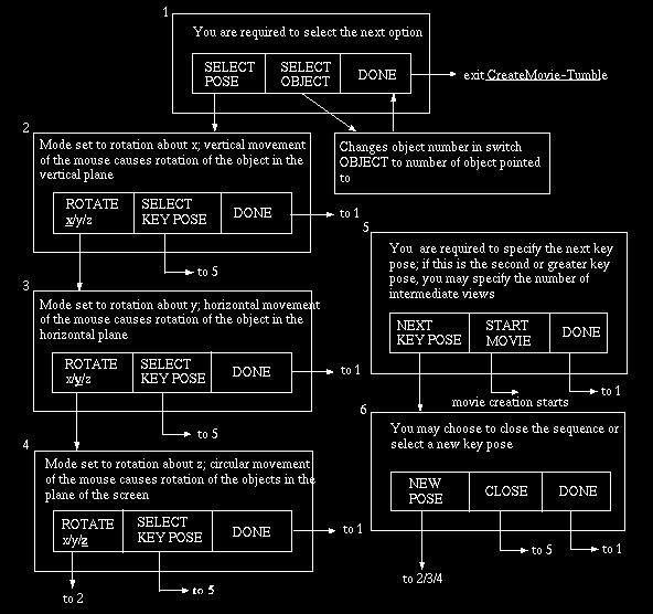
Fig 11.16: State diagram for CreateMovie-Tumble. An arrow leaving a mouse
button area indicates that that button has been clicked.
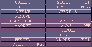
Fig 11.17: Panel options for CreateMovie-Tumble.
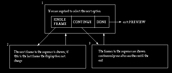
Fig 11.18: State diagram for PREVIEW option of CreateMovie-Tumble. An arrow
leaving a button area indicates that that button has been clicked.
11.3.8.2 CreateMovie-PreviousSeq
The purpose of this command is to make it possible to create a movie for
the most recently specified sequence of key poses. This specification
need not be in the current session of 3DVIEWNIX. The idea here is that
when repeated types of 3D imaging operations are done on a large number
of data sets, user time can be saved by allowing a one-time
specification of a movie protocol. Movies can then be generated
automatically for the different data sets. If no key pose sequence has
previously been specified, the command will complain so and will not
create a movie.
Fig 11.19: Panel options for CreateMovie-PreviousSeq.
 User Manual
 Library Ref. Manual
 Tutorial